


Our “MECH-JOINT” Rebar couplers are based on Globally approved & Patented Parallel threaded mechanism where the The Ends of the Reinforcement Bars which are tobe joined shall be enlarged by Cold FORGING and Threaded in such a way that the Diameter of root of the threads shall is not lesser than Parent Bar. There is no process of removal/area reduction of steel Unlike other threading processes. In contrary, there is an increase of strength of the reinforcement to the tune of 15% due to hardening process.
The most Effective feature of this system is its ability to withstand higher fatigue strength as the material grains are not removed/disturbed other than realigning of material to form threads.
It is designed to withstand any stringent load conditions in Full Tension and assured for 100% Barbreak performance which is far more than the Parent bars being used. Our Products are designed and manufactured in compliance with ACI318, JGJ107,UBC 1997, BS8110, BS 5400-Part 4, NF35-20-1, DIN1045, ISO/WD 15835 (Draft), BIS 456, IRC 2000 etc. Our Parent Materials of Couplers are having adequate Ultimate Tensile Strength of more than 150% of the Reinforcement bars ie. 700 N/mm2 and hence a coupled Joint shall able to withstand for Yield Tensile Strength of more than 125% of Reinforcement bars.
It is also designed to withstand Cyclic loading, Low Fatigue, High Fatigue, Cyclic Tension-Compression, Slip Test, Strain Tests etc., which are essentially considered asper current BIS DRAFT codes to qualify the Couplers system.
AMENDED SPECIFICATIONS OF “MECH-JOINT”-COUPLERS AS PER INTERNATIONAL STANDARDS(WEF.01-09-2014)
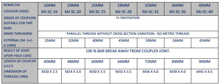
CHECKING INSTRUMENTS :
Vernier Calipher, Thread Guages, Go-No-go Guages, Pipe wrench, Torque wrench.
METHOD STATEMENT FOR THREADING PROCEDURE :
- Rebar are cut to lengths at the steel fabrication yard before transfer by crane on to the threading work bench.
- Poorly sheared ends shall be cut off by Heavy Duty Bandsaw Cutting Machine prior to any threading work.
- Rebar ends tobe threaded shall be engaged to the Cold Forging Machine whereby the Edges of the Bars are enlarged to aCertain Defined Diameter using Heavy duty Mould/Punch Systems alongwith Hydraulic Pressure Guages.
- The Bars having Enlarged Ends are then shifted to the threading machine head to commence threading. Threading head automatically disengages once a full thread length is completed.
- A coupler guage with cutwindow (or) the Half portion of couplers on which the start and End point of threads are seen visibly for verification of its proper alignment.
- A coupler capped at one end shall be hand-locked onto the threaded bar ends. All exposed threaded bar ends shall be protected with plastic caps.
- Rebar threaded and scheduled for installation are transferred by crane to site.
INSTALLATION PROCEDURE FOR TORQUE TIGHTENING VERIFICATION :
The Installation of the splicing coupler is usually performed on site by Steel Bar benders/Fixers and the Procedure shall be as Follows. Torque wrenches are used specifically for the purpose of measuring joint tightness. The table for qualification of tightening is furnished below for reference purposes. For the purpose of tightening rebar couplers a 14 inch pipe wrench shall be used by first simulating the tightening process of a preset torque wrench.
- Insert the threaded bar end into the coupler until it is in its correct position and ensure that the threaded bar end is properly engaged into the coupler. A practical verification of non-exposure of threads confirms the proper alignment of coupler with the bar.
- Tighten by hand until the splice is firm before using the torque wrench. Generally the torque wrench is supplied by Client/Contractor and used for joint checking of each joint with Splicing contractors.
- Turn the torque wrench to tighten the connection until a “Click” sound is heard.
- Check whether the coupler is properly locked into the reinforcing bars.
- Repeated the same process for other end.

THE SETTING INSTRUCTIONS FOR MAXIMUM TORQUE VALUE ON THE RECOMMENDED WRENCH IS AS FOLLOW:
- Insert the special key into the locking at the far end of the hand grip.
- Turn the locking nut until the desired torque value appears in the display window.
- Remove the special key and torque value is set.
MACHINE ASSEMBLY AT SITE
UPSET FORGING, PARALLEL THREADING AND HEAVY DUTY BANDSAW CUTTING MACHINES MACHINES
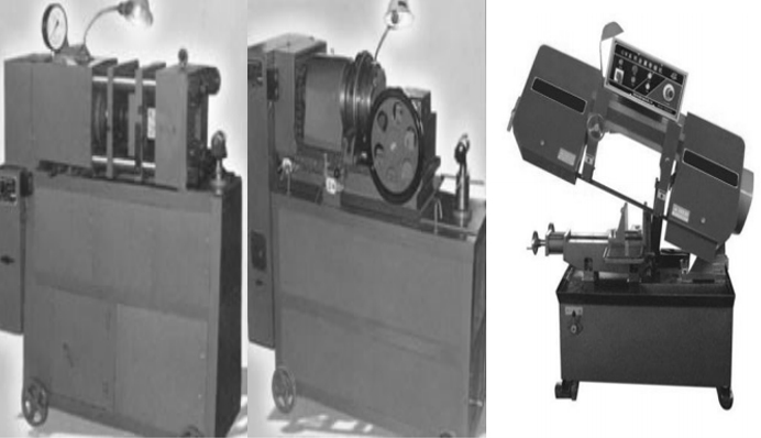
DESCRIPTION OF MACHINE :
- Suitable for rebar sizes 16mm – 40mm dia.
- Maximum of 8-10 hp power requirement for motor.
- Min. productivity of 300-400 threads per shift.
- Area needed for machine setup : 8 feet x 8 feet for machines and enough space to make steel bed and rotation of bars in front of machine.
- levelled platform and shed need tobe arranged for loading machines to achieve proper storage.
- Scrap steel or cutpieces of bars shall be provided to make a steel bed infront of the machine.
- Handling labours.
.